What is a Switch Mode Power Supply & Inductor? (SMPS)
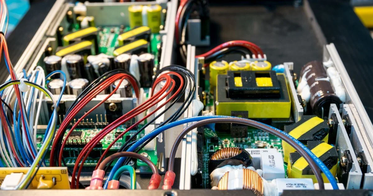
Power conversion is everywhere. Every piece of equipment that takes voltage from a wall or DC bus and turns it into something usable has a power supply doing that work. For decades, linear supplies were the standard: simple, quiet, and reliable, but heavy, large, and wasteful with heat. The switch mode power supply replaced them in most applications, and the reasons are straightforward.
Knowing what an SMPS does and what role the inductor plays in it helps you make better decisions early in the design—before you're chasing noise problems or troubleshooting heat on a finished board.
How a Switch Mode Power Supply Works
A linear supply regulates output by burning off excess energy as heat. An SMPS takes a different approach. It switches the input voltage on and off at high speed, then uses magnetic components to store and release energy in controlled pulses.
Output voltage is regulated by adjusting how long the switch stays on each cycle, which is the duty cycle. A longer on-time delivers more energy to the output. A shorter on-time delivers less. Because energy transfers in bursts rather than being wasted as heat, efficiency climbs fast.
A well-designed SMPS typically runs at 85–95% efficiency. A comparable linear supply might manage 40–60%. That gap matters in high-power applications where heat management directly affects system size and long-term reliability. It also matters for enclosure design: less heat means smaller thermal management hardware and more flexibility in how the overall system is packaged.
The switching happens fast, from tens of kilohertz up to a few megahertz, depending on the design. Higher switching frequencies allow smaller passive components, which is why modern power electronics can pack serious power into compact form factors. But frequency is a trade-off, not a free variable. Higher frequencies increase switching losses and place tighter demands on core material and winding geometry.
The Role of the Inductor in SMPS Design
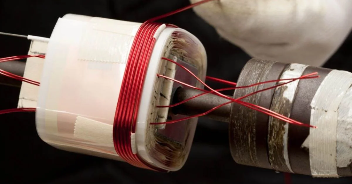
If the switch is the heart of an SMPS, the inductor is the regulator. It stores energy during the on-time and releases it during the off-time, smoothing the pulsed current into stable DC. Without it, the output would be a choppy square wave rather than usable power.
Inductor selection in SMPS design isn't a passive exercise. Get it wrong and you'll see problems that are hard to trace back to the magnetics: output ripple that exceeds spec, instability under load transients, saturation at peak current, or thermal runaway at temperature. In most cases, they're specification mismatches that compound under real operating conditions, not component failures in the conventional sense.
The key parameters:
Inductance value (L): Sets ripple current magnitude. Too low and ripple increases. Too high and transient response slows. The right value depends on switching frequency, input/output voltage ratio, and your ripple specification.
For buck converters, targeting ripple current between 30–40% of applied load current keeps the feedback loop reading a clean signal without pushing into discontinuous conduction mode (DCM). Drop below that range and the SNR deteriorates — the feedback loop starts registering noise as signal.
Saturation current: The point where the core can no longer support further increases in flux density. Once peak current exceeds this value, inductance collapses, and the supply loses regulation. Saturation behaviour varies by core material: powdered iron saturates softly, ferrites can saturate sharply. A good rule of thumb is to select an inductor with a saturation current rating at least 20–30% above your expected peak current.
DC resistance (DCR): Contributes directly to copper losses. Lower is better, but winding geometry and wire gauge involve trade-offs with size and cost.
Core losses: At high switching frequencies, core material drives AC losses more than winding design does. This is where material choice, whether ferrite, powdered iron, amorphous, or nanocrystalline, has a direct impact on efficiency and heat.
Topology Shapes the Inductor Requirement
SMPS design covers several topologies, and each places different demands on the inductor or transformer. In a buck converter, a single output inductor filters the switched waveform. In a boost converter, the inductor stores energy during switch-on and releases it to a higher output voltage during switch-off.
Flyback and forward converters use transformers that also function as inductors, with galvanic isolation built in. The flyback topology is common in low- to mid-power applications because it provides isolation with a single magnetic component. It's a cost-effective choice when output power is moderate and the design needs to meet safety isolation requirements.
But the transformer in a flyback behaves more like a coupled inductor than a standard transformer. Energy is stored in the core gap during switch-on and delivered to the secondary during switch-off. Designing that gap correctly and choosing a core material that handles energy storage without excess losses, is where a custom magnetics design makes a measurable difference.
For full-bridge and half-bridge topologies in higher power designs, the transformer operates differently. Energy transfers continuously rather than in alternating storage and release cycles. Core use is more efficient, but flux symmetry and leakage inductance become critical design variables.
Getting both right requires working through the actual design, not referencing a standard topology diagram.
Switching Frequency and Component Size
One of the most common trade-offs in SMPS design involves switching frequency. Increasing the frequency reduces the required inductance and shrinks the physical component size, which is attractive for tight designs. But it also increases core losses, raises switching losses in the semiconductor devices, and demands tighter control over parasitic elements in the layout.
Higher frequency shrinks the passives, but it doesn't come free. The tension between component size, losses, and noise is real — getting all three right simultaneously usually isn't possible, and frequency is where that trade-off starts.
For magnetics, the frequency dependence is direct. Ferrite cores perform well from 20 kHz up to several hundred kilohertz, with specific grades covering different ranges. The 3C95 and 3F3 grades cover meaningfully different bands. Nanocrystalline cores handle higher flux densities and lower losses at mid-range frequencies, making them well-suited for high-current inductors.
Powdered iron and Kool Mµ materials are common in boost inductors where stored energy is high and soft saturation behaviour matters.
Wire selection follows frequency as well. At higher frequencies, skin effect concentrates current near conductor surfaces, increasing effective resistance. The proximity effect compounds this in multi-layer windings, where adjacent conductors further distort the current distribution.
Litz wire, which consists of bundles of individually insulated strands, reduces both effects in high-frequency inductors where copper losses would otherwise climb. It adds cost and winding complexity, but in some designs, it's not optional if you're trying to hit efficiency targets.
Where Custom Magnetics Fit In
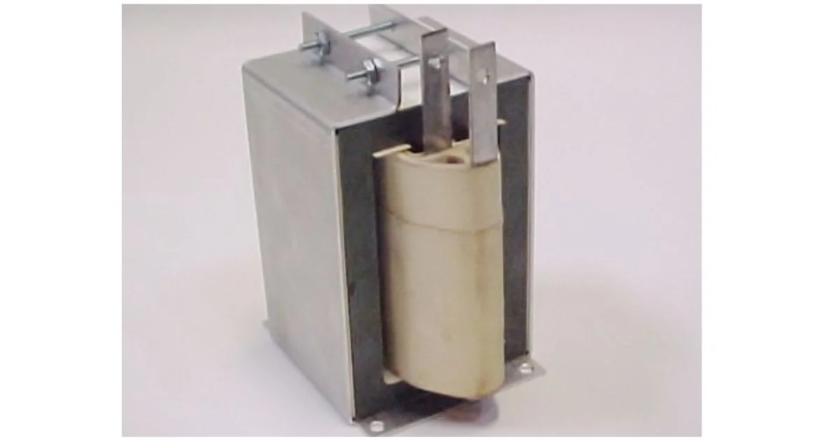
Catalogue inductors cover standard applications, but custom-wound inductors specified for the actual thermal environment make a measurable difference when your design doesn't fit neatly into catalogue specs.
Temperature rating matters more than most designers initially account for. A catalogue inductor rated for 85°C ambient may not withstand higher local temperatures inside enclosures. Custom-wound inductors can be specified to Class F (155°C) or Class H (180°C) insulation systems, with core materials and encapsulation chosen for the actual thermal environment.
High-current applications, such as DC fast chargers, battery energy storage systems, and motor drive front ends, can require nominal currents of hundreds of amps. Building that into a compact component without excess DCR or saturation at peak load means moving past catalogue solutions.
Winding geometry, core geometry, and gap specification all interact. Getting the thermal management right requires engineering time, not just a datasheet lookup. And in safety-critical applications, that engineering needs to be backed by a quality system that can trace every design decision through to the finished part.
Custom SMPS magnetics also give you direct control over leakage inductance, which affects switching waveforms, EMI performance, and snubber requirements. In a flyback transformer, leakage inductance is unavoidable but manageable. Interleaving primary and secondary windings reduces it significantly.
The manufacturer needs to understand both the electrical requirement and how to build to it consistently. Core material selection drives efficiency, heat management, and lifespan — get it wrong and even a well-wound inductor won't save you.
Getting the Specification Right from the Start
Before engaging a magnetics manufacturer for a custom SMPS inductor, document your operating conditions thoroughly. Nominal current, peak current, ripple current, switching frequency, ambient temperature, physical envelope, and isolation requirements are not all the parameters, but they're where a design conversation starts. The more complete that picture is upfront, the faster the design process moves.
If you're working from an existing design that's underperforming, a clear specification helps identify whether the issue is in the magnetics or elsewhere. Saturation at load transients, unusual heat in the inductor, or instability at certain operating points all trace back to specific electrical or thermal parameters, and they each point to different corrections.
Electronic Craftsmen has been designing and building custom SMPS magnetics for over 25 years, with a full range of core materials, winding formats, and encapsulation options available in-house.
If you're working through an inductor specification for an upcoming design, contact our engineering team to discuss your requirements.