Types of 3-Phase Inductors & Chokes for Industrial Use
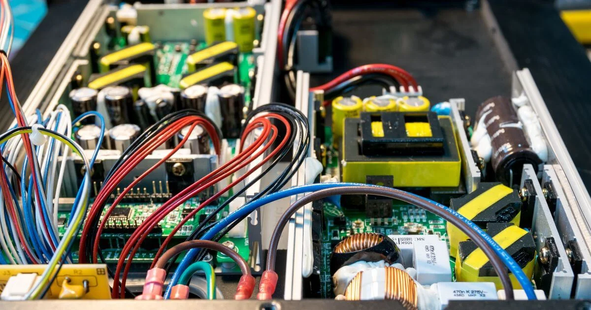
Three-phase power systems power most heavy equipment in industrial facilities. Variable frequency drives, rectifiers, motor controls, renewable energy inverters — they all need clean, stable power to work reliably. The magnetic components managing that power don't get much attention until something goes wrong.
3-phase inductors show up in more places than most engineers expect, and the difference between the various types of three-phase inductors matters. Picking the wrong configuration for a harmonic filtering application, or mismatching an inductor to a rectifier topology, can create problems that take months to trace back to their source. This article covers the main types, what each one does, and where they belong.
Why Three-Phase Inductors Aren't Just Scaled-Up Single-Phase Designs
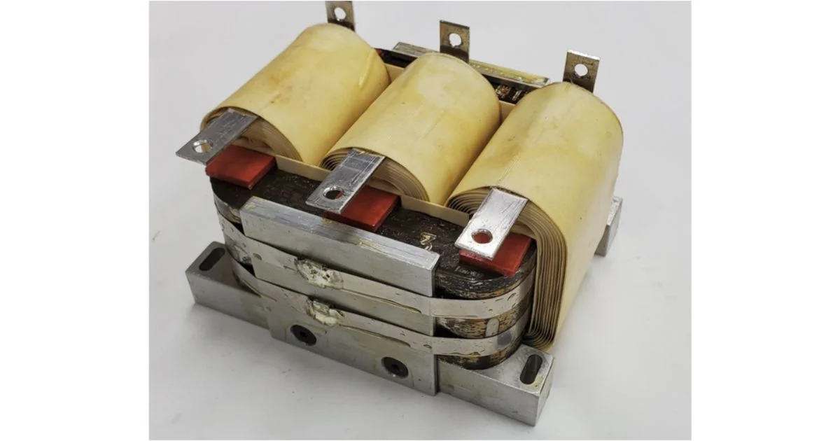
A single-phase inductor manages one winding and one flux path. Three-phase designs balance three. That difference affects core geometry, winding layout, thermal behaviour, and how the component interacts with the rest of the system.
In a balanced three-phase system, magnetic fluxes in each phase are 120° apart. A well-designed three-phase inductor uses that phase relationship, where flux from one limb partially cancels flux in another. That allows for smaller cores compared to three separate single-phase units. In practice, load imbalances, harmonic content, and non-sinusoidal waveforms push the design harder than nameplate conditions suggest.
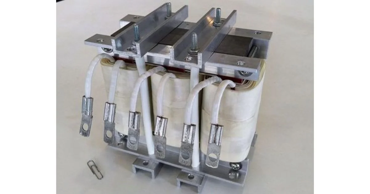
Core construction varies by application. Stacked lamination cores work well at line frequency. Ferrite and powdered iron cores handle higher switching frequencies better. The gap geometry, whether distributed or discrete, shapes saturation behaviour and affects performance under transient loads.
If you're working through whether a single three-phase unit or three separate inductors makes more sense for your design, our inductors, chokes, reactors, and filters breakdown covers that distinction in more detail.
AC Line Reactors: The Workhorse of Industrial Power Conditioning
AC line reactors are the most common three-phase inductors used in industry. They sit on the input side of variable frequency drives, soft starters, and rectifier bridges. Their job: limit the rate of current rise, reduce harmonic distortion fed back into the supply, and protect upstream equipment from voltage notching.
A 3–5% impedance line reactor at the VFD input can reduce total harmonic distortion (THD) from 80–100% to 35–40%, depending on drive topology and load. That matters under IEEE 519, which sets harmonic distortion limits at the point of common coupling. Distortion from one large drive or a dozen smaller ones adds up at the service entrance all the same.
Line reactors also extend drive life. The capacitor banks inside a VFD see less stress when there's a reactor on the input, because current peaks that charge those capacitors are flattened. It's one of the less expensive ways to improve system reliability.
One important distinction: line reactors aren't interchangeable with DC link chokes. Both appear in VFD applications, but the DC link choke sits inside the drive between the rectifier and inverter sections, targeting a different part of the harmonic spectrum. Some manufacturers include one or the other from the factory, so checking drive documentation before specifying an external reactor avoids confusion.
Output Reactors: Protecting Motors and Long Cable Runs
Output reactors go on the load side of a VFD, between the drive and the motor. The concern here is different from the input side. High-frequency switching transients from the drive's IGBT inverter produce voltage spikes with rise times in the nanosecond range. Those spikes reflect off cable impedance discontinuities and can double the voltage at motor terminals.
In long cable runs, that problem compounds quickly. A 600V drive on a 100-metre cable run can produce motor terminal voltages exceeding 1,200V without output filtering. That stress degrades winding insulation over months, not years. The failure often looks like random motor burnout rather than a drive issue, which is what makes it hard to catch.
Output reactors slow the rate of rise of voltage (dV/dt), reducing the reflected wave magnitude and protecting motor insulation and cable. NEMA MG1 Part 31 specifies that inverter-duty motor insulation systems for motors rated at 460V should withstand peak terminal voltages up to 1,426V, a threshold that long cable runs can exceed without output filtering.
The DOE's inverter-duty motor guidance notes that damaging reflected waves are generally not a concern when the cable run between drive and motor is under 15 feet (roughly 5 metres), but the risk rises quickly beyond that. For applications running motors more than 30 metres from the drive, an output reactor should be included in the original design rather than in the retrofit budget after the first motor failure.
Common-Mode Chokes: Targeting a Different Kind of Noise
Common-mode chokes address a noise type that differential-mode inductors can't touch. Common-mode currents flow in the same direction on all three conductors and return through the ground path. They don't cancel in the core; they add.
In VFD applications, the inverter's switching action generates common-mode voltages that drive high-frequency currents through motor bearing lubricant films. Over time, those currents cause pitting in the bearing races, a failure mode called electrical discharge machining (EDM) damage. Bearings that should last years start failing in months, and post-mortem inspections don't always pinpoint the real cause.
A common-mode choke on the drive output presents high impedance to those currents without affecting the differential load current. The three-phase conductors pass through a single core, differential flux cancels, and the choke only acts on what it's designed to stop.
Common-mode filtering is often specified alongside output reactors in sensitive applications, including precision manufacturing, medical equipment, and systems where ground current creates measurement interference.
Harmonic Filtering Inductors and Passive Filter Assemblies
Harmonic filtering inductors target individual harmonic frequencies rather than provide broadband impedance. They're used in passive LC filter assemblies, where the inductor resonates with a capacitor bank at a specific harmonic order, creating a low-impedance path that pulls harmonic current away from the supply.
A 5th harmonic filter tuned to 300Hz (in a 60Hz system) is the most common single-stage passive filter in industrial use. Facilities with 6-pulse rectifier loads, including large drives, UPS systems, and battery chargers, generate 5th and 7th harmonics as the dominant orders. Passive filters targeting those frequencies can bring THD to levels that satisfy IEEE 519 without active filtering equipment.
The inductor design in a passive filter is more demanding than a standard line reactor. Inductance tolerance has to stay tight across the operating current range, because the resonant frequency shifts if inductance drifts under load. Core saturation is also a real risk, as harmonic filter inductors sometimes carry a mix of fundamental and harmonic current that pushes the core harder than the fundamental rating alone suggests.
For facilities with diverse load profiles or loads that vary significantly from shift to shift, passive filters can fall short. Active harmonic filters handle variable harmonic spectra better, but at considerably higher cost and complexity. For applications where the harmonic content is reasonably consistent and THD requirements are well-defined, a well-designed passive filter built around tight-tolerance custom inductors is often the more practical path.
Multi-Pulse Magnetics: Cancelling Harmonics at the Source
Multi-pulse rectifier configurations use transformer phase-shifting to cancel harmonic orders at the source. A standard 6-pulse rectifier generates 5th, 7th, 11th, and 13th harmonics as dominant terms. A 12-pulse system, using delta-wye and delta-delta transformer combinations to create two 6-pulse rectifiers phase-shifted by 30°, cancels the 5th and 7th harmonics. The 11th and 13th remain, but at much lower amplitude.
An 18-pulse system pushes further, cancelling through the 17th harmonic order. It's common in large drive applications where utility harmonic limits are strict or where the installation is near sensitive equipment.
Multi-pulse configurations require careful attention to load balance across parallel rectifier paths. If one path carries more current than another due to impedance mismatch, harmonic cancellation degrades. The magnetics have to be matched, not just nominally rated for the same current, but wound to close impedance tolerances so current sharing stays within design limits across the load range.
That's where catalogue components often fall short. For a closer look at the transformer configurations that make multi-pulse systems work, our wye vs. delta connections post covers the phase relationships behind these designs.
Matching the Right Inductor to the Job
The type of three-phase inductor a system needs depends on where the problem is, what harmonic orders are present, and what the downstream equipment can tolerate.
Line reactors handle input-side harmonic reduction for most VFD applications. Output reactors protect motors and cables in long-run installations. Common-mode chokes address bearing currents and ground noise that differential inductors don't affect.
Harmonic filtering inductors target specific frequency components in passive filter assemblies. Multi-pulse magnetics tackle harmonic content at the source for large rectifier loads. These aren't interchangeable, and many installations need more than one type.
A large industrial drive with a 50-metre cable run in a facility with strict IEEE 519 requirements might need an input line reactor, an output reactor, and a common-mode choke, each doing a different job. Getting the design right matters. Inductance value, saturation current, impedance tolerance, core material, and thermal rating all have to match actual operating conditions.
For applications where standard parts don't fit, whether that's unusual voltage levels, non-standard frequencies, tight harmonic limits, or demanding environments, custom-designed 3-phase inductors are the more reliable path. We've been designing and building custom three-phase magnetics for industrial, aerospace, and power electronics applications for over 68 years.
If your application has requirements that catalogue parts can't meet, reach out to our team and we'll work through the design with you from initial specification to production-ready units.