The Role of 3 Phase Power and Custom Magnetics in Data Centres
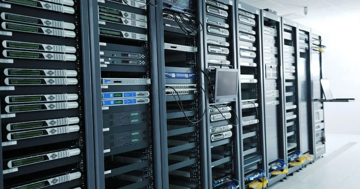
Data centres don't run on good intentions. They run on power, and lots of it. And that power has to be delivered reliably, at the right voltage, with minimal losses at every step of the distribution chain.
When that chain breaks down, so does everything else. Server racks go offline. Cooling systems fault. UPS units absorb demand they weren't sized to handle continuously.
The scale of what's being asked of these facilities is growing fast. According to the IEA, electricity demand from data centres rose 17% in 2025, well ahead of global demand growth of 3%. It's projected to double by 2030.
AI-focused facilities are on a steeper trajectory still. The same IEA report called out transformers as a supply chain bottleneck. They're one of the physical limits on how quickly new data centre capacity can come online.
That bottleneck reflects something engineers in this space already know. The magnetic components in a data centre power system aren't passive infrastructure. They're load-bearing. Get the specification wrong, and you're chasing problems that don't show up until something critical has already degraded.
Three-phase power distribution is where that conversation starts.
Why Three-Phase Distribution Is the Only Realistic Option at Scale
Single-phase power works for small loads. It doesn't work for data centres. Three-phase distribution delivers power more efficiently across large facilities. The three voltage waveforms are offset by 120 degrees. That offset produces a constant, smooth power flow instead of the pulsing delivery you get from single-phase systems. It matters when you're running continuous loads with zero tolerance for voltage sag.
Three-phase systems also transmit the same power with less copper than an equivalent single-phase installation. In a facility where distribution runs span tens of thousands of square feet, resistive losses compound quickly.
Three-phase loading also balances across all three phases. That reduces neutral current and the heat that comes with it, which matters for insulation life over long service periods.
The transformers stepping voltage down at each stage are the mechanical interface between the utility feed and the IT equipment. Their design determines how much incoming power reaches the load versus how much is wasted as heat.
What Nonlinear Loads Actually Do to Your Distribution System
Servers, UPS inverters, variable speed fans, and switched-mode power supplies are all nonlinear loads, and that's where distribution design gets harder to get right. They don't draw current in a smooth sinusoidal pattern. They pull current in bursts, injecting harmonic distortion back into the distribution system.
Harmonic currents do more than cause nuisance tripping. They create additional heating in transformer windings and cores. That accelerates insulation degradation in equipment expected to run continuously for 10 to 20 years. The result: harmonic distortion forces transformers to derate from nameplate capacity. That happens when they weren't designed with harmonic loading in mind.
IEEE 519-2022 sets the limits for voltage and current distortion at the point of common coupling. That's the interface between the facility's internal distribution and the utility. Meeting those limits isn't optional for facilities with significant nonlinear load profiles. But compliance at the service entrance doesn't protect transformers deeper in the distribution chain. Those units still see the harmonic currents generated internally by server and UPS loads.
That's where IEEE C57.110-2018 comes in. It provides methods for calculating whether an existing transformer can handle nonsinusoidal load currents. It also guides the specification of new transformers in which harmonic loading needs to be built into the design from the start.
Running a standard distribution transformer at full nameplate capacity in a heavy switching environment shortens its service life considerably.
Specifying Transformers for Data Centre Environments
A transformer specified for a conventional industrial application and one specified for a data centre are solving different problems.
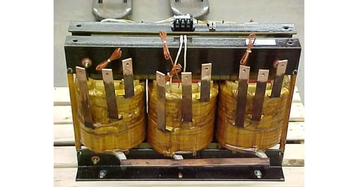
Three-phase transformers in data centres are typically dry-type units at the facility level, often in unit substation configurations. Smaller step-down units sit closer to the point of use. Each stage introduces loss. The cumulative effect shows up in power usage effectiveness, or PUE.
Every conversion loss in the power chain pushes PUE — total facility energy divided by IT energy consumed — further from the ideal. Transformer losses are part of that calculation at every stage.
Minimizing transformer losses in a high-harmonic environment starts with core material selection. The core needs to handle distorted waveforms without saturating. Winding configurations need to reduce eddy current losses at elevated frequencies.
Insulation class needs to match actual operating temperatures, not nameplate assumptions. Class F insulation or higher is common in data centre transformer specifications. Harmonic content raises operating temperature even at loads that would be routine in a clean sinusoidal environment.
Winding configuration also determines how harmonics move through the system. Delta-wye and wye-delta arrangements trap certain harmonic orders, particularly third harmonics and their multiples. That prevents them from propagating upstream to the utility or downstream to sensitive loads.
For facilities running significant server loads, it's a technical requirement. Without it, the facility can't stay within IEEE 519-2022 limits at the point of common coupling.
The choice between wye and delta configurations isn't just about voltage compatibility. It directly affects which harmonic orders get trapped and which propagate through the system.
Where Custom Magnetics Fit into the Data Centre Power Chain
Off-the-shelf transformers are designed to a general specification. Data centre power environments are specific, and the specifics matter.
Custom magnetics for data centre power let engineers specify winding configurations, core materials, insulation class, enclosure type, and harmonic derating. All of it in one integrated design. For facilities with unusual footprints, high-density rack configurations, or dedicated onsite generation, that flexibility is directly tied to long-term reliability.
The IEA projects that electricity consumption from AI-focused data centres will triple by 2030. That means more nonlinear load density per square foot and more harmonic content in distribution systems. It also puts more pressure on components specified when the facility's load profile looked very different.
Custom inductors in three-phase filter designs carry more weight than they're usually given credit for. Harmonic filters at the point of common coupling depend on precise inductance values to work across the harmonic frequencies of interest. The same applies to filters at the input to large UPS systems.
An inductor close to specification behaves differently from one that hits the target exactly. That difference matters most at the 5th and 7th harmonics, which dominate switched-mode power supply environments.
Reliability Under Continuous Load: A Design Requirement, Not an Afterthought
Data centres don't get planned maintenance windows the way industrial facilities do. Power distribution failures in data centres rarely announce themselves. Insulation degradation, harmonic-driven overheating, and winding breakdown accumulate over months before anything trips.
Magnetic components run continuously. Cooling systems are working hard. Ambient temperatures can exceed the standard design environment assumed in a nameplate rating. Add harmonic loading on top, and the thermal picture gets worse.
Vacuum Pressure Impregnation (VPI) using electrical-grade varnish improves long-term winding reliability in continuous-duty applications. It penetrates the winding structure and eliminates voids where moisture or contaminants could accumulate. Encapsulation with appropriate materials adds mechanical stability for facilities that deal with vibration from cooling infrastructure or backup generators.
Thermal cycling tests across the full operating range verify performance under actual conditions, not ideal ones. Testing as required by the application, rather than to a minimum standard, is how you catch problems before they become unplanned outages.
Integrated Magnetic Design: Where Space and Efficiency Overlap
Consolidating magnetic functions into a single component reduces footprint and failure points per power conversion stage. Incorporating inductance into a transformer's primary winding removes the need for a separate line reactor entirely.
In high-density facilities, floor space is rack capacity, and rack capacity is revenue. That consolidation has practical value beyond the efficiency argument. Fewer discrete components means fewer failure points, fewer maintenance intervals, and simpler documentation for the facility's quality system.
This is most relevant for three-phase filter designs at the input to large rectifier stages. A properly specified integrated magnetic component handles the inductive filtering function and the voltage transformation in one unit, replacing two separately sourced components with a single engineered solution.
Getting the Specification Right Before the Build
The most expensive magnetics problem in a data centre is the one found after installation. Replacing a transformer in a live unit substation costs far more than a thorough upfront specification. Tracking down harmonic-driven insulation failure in an active distribution chain costs more still.
The specification process works best when it starts with the real load profile. Not the peak theoretical load. The actual harmonic content, the duty cycle, the ambient conditions, and the facility's growth trajectory. A manufacturer with experience in high-harmonic, continuous-duty environments can build from that profile to a design that holds up over the facility's operational life.
Electronic Craftsmen has been designing custom magnetic components for over 68 years. Applications include rail power systems, renewable energy infrastructure, and industrial automation, where continuous duty and harmonic loading are standard conditions.
With a database of over 10,000 proven designs and engineers on-site, the team can typically develop a firm quote within a week.
If you're specifying magnetics for a new data centre build or a capacity expansion, contact us to discuss your requirements.