Common Causes of Transformer Failure (and How to Prevent Them)

Ever had equipment fail at the worst possible moment? A system shuts down, alarms sound, and suddenly critical operations grind to a halt. It's frustrating, costly, and sometimes dangerous.
Although rare, Transformers do fail, but there are usually contributing factors. Overheating, insulation degradation, and short circuits are three of the most common causes for transformer failure. For example, overheating due to load failures or overloading can degrade insulation performance over time until the transformer prematurely fails.
For engineers, that means downtime, replacement costs, and pressure from teams counting on reliable power. For procurement teams, it means warranty claims, unexpected maintenance budgets, and contracts that start looking riskier than expected.
The good news is these failures aren't inevitable. They're predictable, measurable, and most importantly, preventable. With the right approach to transformer design and manufacturing, these problems can be avoided before the first unit is ever deployed.
That's where custom power transformers prove their value. Built to meet application-specific requirements, they add resilience into systems where failure isn't an option. At Electronic Craftsmen, we've seen how proper design prevents these common failures.
This article breaks down the most common causes of transformer failure and shows how practical design and testing strategies can prevent them in real-world applications.
Managing Transformer Overheating Risks
Heat is one of the most consistent enemies of transformer reliability. Excessive temperatures cause winding insulation to harden, crack, and eventually fail. Overheating speeds up material breakdown, often happening gradually with few visible signs until the transformer fails.
Several factors push transformers beyond safe operating limits. Overloading is a common one, especially when systems expand and demand more power than originally planned. Poor ventilation and restricted airflow also create local hot spots that insulation systems can't withstand.
Even the surrounding environment plays a role. A transformer that performs well in a controlled lab may fail quickly when exposed to desert heat or Arctic cold. Temperature ratings give you a clear sense of what a transformer can tolerate.
Most industrial designs use Class F insulation systems, rated for 155°C, but transformers can be specified for higher classes up to 220°C when required. Testing capabilities also matter. Thermal cycling from –73°C to +190°C helps verify that windings, insulation, and core materials won't degrade in extreme operating conditions.
Without this kind of validation, you can't be confident about how equipment will behave when real-world temperatures fluctuate. The impact of ignoring thermal risks is significant. In aerospace power systems, overheating can cause flight-critical failures.
In renewable energy applications, excess heat means downtime and lost production during peak demand. In every case, heat-related failure leads to expensive replacement costs and reduced trust in the system's reliability.
According to Natural Resources Canada, winding losses and core heating are responsible for much of a transformer's long-term inefficiency. By optimising conductor design and specifying higher-grade core materials, many of these losses can be reduced.
The practical approach is straightforward. Design conservatively. Specify insulation ratings that match the environment. Validate performance with thermal cycling and load testing.
Preventing Insulation Breakdown in Transformers
Transformer insulation doesn't usually fail all at once. Manufacturing defects, FOD, and Environmental conditions can speed up the process.
For example, high humidity environments can create tracking paths across insulation surfaces leading to premature failure.
Electronic Craftsmen uses custom varnishing equipment to coat products in electrical grade varnish to help mitigate the environmental impact on transformer longevity. In addition, a Vacuum Pressure Impregnation (VPI) process can be specified to ensure complete varnish penetration into the coil windings.
In High voltage encapsulated applications, problems often begin at a microscopic level. Partial discharges within tiny voids of poorly encapsulated transformers grow over time degrading the intended insulation properties of the transformer.
Left unchecked, these manufacturing defects reduce dielectric strength until insulation can no longer withstand operating voltage. When that happens, the result is catastrophic failure.
At Electronic Craftsmen, our encapsulation process uses state of the art processing equipment capable of vacuum encapsulation down to 100 mTorr to eliminate voids and ensure the potting medium fully penetrates the coil. This Ensures a void free encapsulation and eliminates the risk of premature insulation breakdown.
In addition, Corona discharge testing capabilities up to 30kVac allows partial discharge detection down to 2pC identifying potting issues before they reach the field. Together, these measures contribute to insulation systems that can survive decades of real-world operation.
Foreign object debris or foreign object damage in aviation (FOD) can damage transformer insulation, creating weak points that accelerate insulation breakdown. What starts as a small imperfection becomes a short between windings or from winding to ground. Preventing these failures requires a robust process free from the risk of FOD, precision manufacturing, and rigorous testing.
The business consequences of insulation failure are immediate and severe. In communications infrastructure, it can mean signal outages and service disruptions. In medical equipment, it may compromise patient safety or force a shutdown mid-procedure. Both outcomes result in costly downtime and reputational damage.
Canadian standards reinforce the importance of insulation performance. Transformers must meet strict dielectric and insulation requirements for approval in regulated markets.
These standards ensure that only designs with verified reliability make it into critical applications. By following them and adding enhanced measures like vacuum encapsulation, you reduce the risk of unexpected breakdowns.
Avoiding Transformer Shorts with Precision Winding
Unlike overheating or insulation degradation, internal short circuits are considered catastrophic. A winding short can occurs between turns, layers, or phases, the result is usually immediate failure.
Often, the fault current is high enough to destroy windings, damage cores, and trigger cascading system shutdowns. That's why preventing shorts isn't just a design concern, it's a precision manufacturing requirement.
Manufacturing defects are often subtle. Missing insulation material, wire that isn’t spaced correctly or has insulation damage, and windings that aren’t isolated correctly can lead to breakdown. Even minor inconsistencies between production runs can raise the risk of premature shorting in critical applications.
Prevention depends robust manufacturing processes, state of the art manufacturing equipment, and a recognized quality control system.
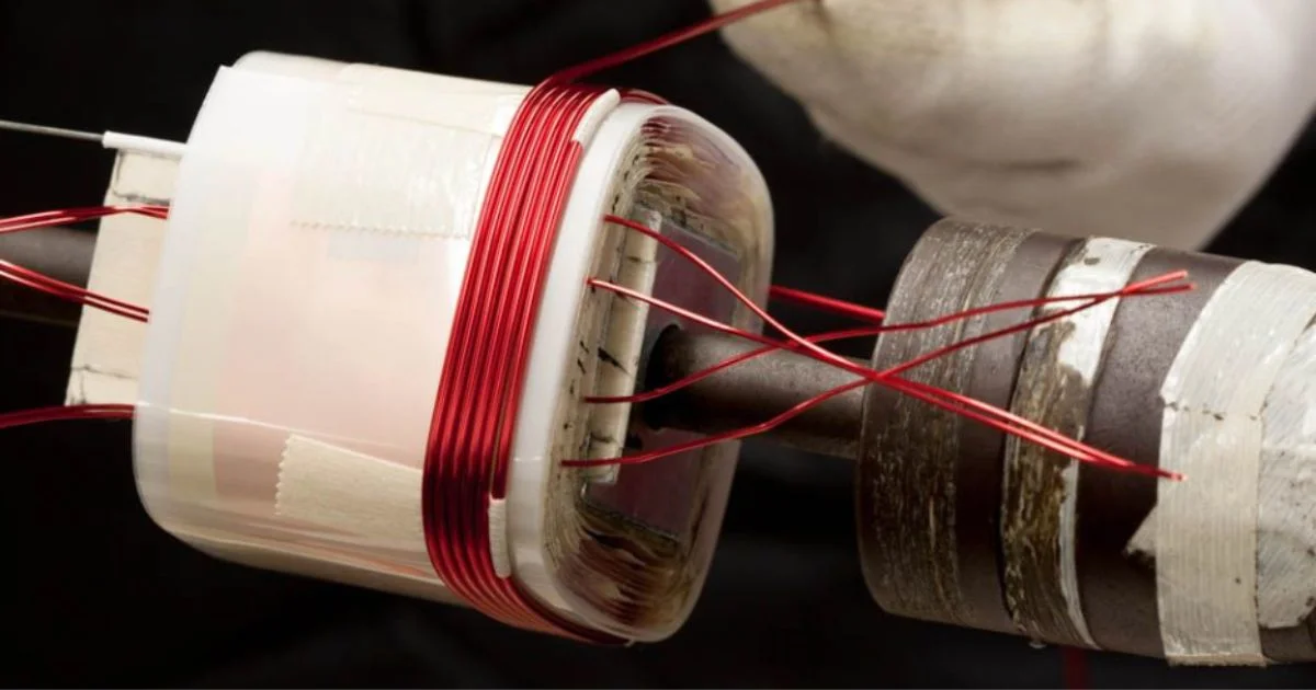
CNC-controlled winding systems with tight tolerance control create repeatable coils that reduce the risk of cross-turn faults. For higher-current products, rectangular or foil windings are installed to distribute current evenly while maintaining clearance distances.
Automated testing systems with tolerances to 0.05% guarantee quality control.
The combination of these key manufacturing elements provides confidence that the products will perform reliably under the most demanding applications.
The consequences of overlooking short-circuit risks are severe. In rail or marine systems, a failed transformer can halt service, disable power, and create costly safety risks.
According to the Canadian Centre for Occupational Health and Safety (CCOHS), The Canadian Electrical Code (CSA C22.1) establishes national requirements for safe electrical equipment and installations. These standards ensure that transformers used in regulated applications meet minimum insulation and dielectric safety requirements.
Quality Manufacturing in Custom Power Transformers
Even the strongest design can fail if it isn't manufactured consistently. A transformer that looks perfect on paper may fall short when winding tolerances slip, encapsulation isn't uniform, or testing steps are skipped. These gaps turn potential reliability into real-world breakdowns.
That's why manufacturing quality matters as much as design. An AS9100 & ISO9001 registered manufacturer operates with proven processes for documentation, traceability, and consistency. Those standards ensure each transformer is built and validated the same way, whether it's a one-off prototype or a full production run.
For industries like aerospace, renewable energy, or industrial automation, this consistency is what protects against failure. Testing is part of that assurance. Not every application requires the same checks, but having capabilities available when specified makes a measurable difference.
Corona testing, thermal cycling, and automated performance verification confirm that insulation, winding, and core systems meet requirements before installation. By catching weaknesses early, manufacturers reduce the chance of failures appearing in the field. For a deeper look at how testing protects long-term performance, see our post on Testing and Quality Assurance for Custom Magnetics.
Supply chain oversight also plays a role. Offshore production may be used, but quality depends on how components are managed. When incoming parts are retested and verified against the original design, the risk of defects slipping through falls dramatically. That attention to detail keeps performance consistent across industries from rail to communications infrastructure.
Research supports this approach. As highlighted in our post on transformer core materials, advancements in transformer core technologies only deliver results when paired with strong quality systems. Without consistent execution, even the most advanced materials can't prevent failures.
The message is simple. Building reliability into transformers requires more than smart engineering. It requires disciplined, repeatable manufacturing practices that keep quality from slipping at any stage.
Designing Out Transformer Failure Risks
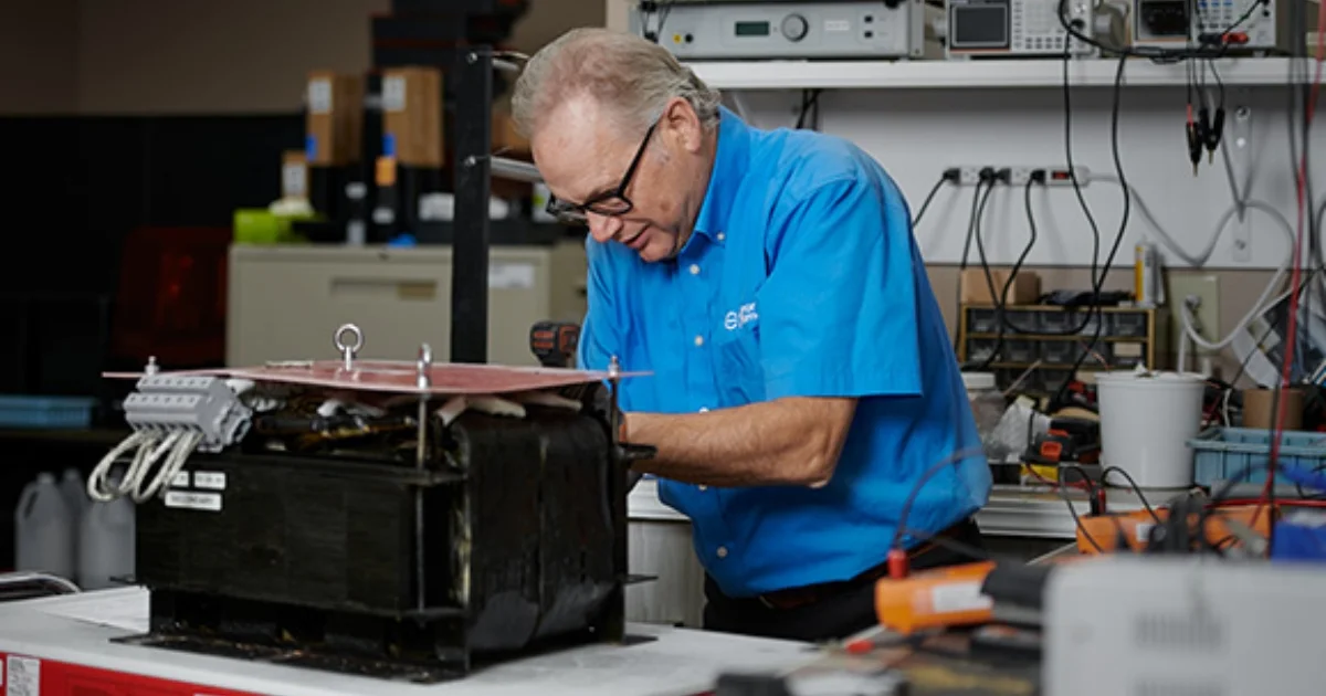
Overheating, insulation breakdown, and short circuits account for most transformer failures. Each damages performance in different ways, but all can be prevented. With sound design, targeted testing, and consistent manufacturing, transformers can operate reliably for decades.
The risks are real across every sector. In aerospace, even brief failures compromise safety. In renewable energy, downtime during peak demand means lost revenue. In industrial automation, an outage halts production and drives up costs. Reliability isn't optional. It has to be designed in from the start.
The most effective strategy is to validate insulation systems through corona testing, hold winding tolerances with automated checks, and confirm thermal stability through cycling. These measures ensure transformers meet real-world demands before installation, not after failure.
If transformer failures are slowing your projects or adding risk, it's time to act. Talk to us about building custom power transformers that eliminate these weak points and align reliability with your exact application requirements. Because when failure isn't an option, neither is leaving reliability to chance.